This simple electronics project demonstrates magnetic induction using two coils and a single transistor.
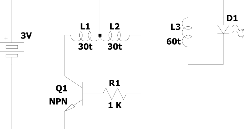
Transmitter coil: approximately 60 turns, 4 cm diameter, with a centre tap
Receiver coil: approximately 60 turns, 4 cm diameter
 How does it work ?
The first coil forms part of a simple transistor oscillator.
When power is applied, current starts flowing through the transistor and one half of the coil. The resulting magnetic field induces a voltage in the other half of the coil. This voltage is fed back to the transistor through the 1 kΩ resistor.
The magnetic field continues to increase until the coil reaches its practical limit and the current can no longer increase in the same way.
Once the current stops increasing, the changing magnetic field that was providing the feedback is no longer maintained.
The feedback voltage therefore falls sharply.
The magnetic field then collapses rapidly.
This sudden change in magnetic flux produces another induced voltage in the coil.
The process then starts again, causing the transistor to switch on and off repeatedly.
The result is a continuously changing magnetic field around the transmitter coil.
The changing magnetic field produced by the transmitter passes through the receiver coil.
This induces a voltage in the receiver coil, which is connected directly to the LED. The induced voltage causes current to flow through the LED, making it light.
Electronics component Fun Kit (with breadboard & power supply module)
General purpose transistors - BC547 (NPN) & BC557 (PNP) pack
Disclosure: As an Amazon Associate, I earn from qualifying purchases. When you click these links to make a purchase, it helps support this website at no absolute extra cost to you.
 INDEX
