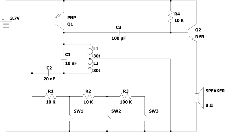
This project is a simple audio oscillator built around a single PNP transistor, an inductor, two capacitors and a few resistors. A separate NPN transistor amplifier stage drives an 8 Ω speaker.
Three switches change the oscillator frequency by adding resistors to the circuit. Increasing the resistance lowers the tone produced by the speaker.
Coil: approximately 60 turns, 4 cm diameter, with a centre tap
 How does it work ?
The circuit consists of two main sections: an LC oscillator and an audio amplifier.
The oscillator
The inductor and capacitors form a resonant LC circuit. Energy alternates between the magnetic field of the inductor and the electric fields of the capacitors. The resonant circuit favours a particular frequency, producing a waveform close to a sine wave.
The PNP transistor provides amplification, while positive feedback compensates for energy losses and sustains the oscillation.
However, adding more resistance changes the operating conditions of the transistor. This adjustments distorts the waveform, moving it away from a perfect sine wave and creating a sound richer in harmonics. It also increases the internal RC time delays, which lowers the frequency of the oscillator. As a result, the sound produced by the speaker becomes lower in pitch.
The audio amplifier
The oscillator generates the audio-frequency signal, but it may not provide enough current to drive the speaker directly.
A separate NPN transistor amplifier stage increases the current available to the 8 Ω speaker.
The speaker converts the amplified electrical signal into sound.
Electronics component Fun Kit (with breadboard & power supply module)
General purpose transistors - BC547 (NPN) & BC557 (PNP) pack
Disclosure: As an Amazon Associate, I earn from qualifying purchases. When you click these links to make a purchase, it helps support this website at no absolute extra cost to you.
 INDEX
INDEX